Skip to content

Circuit Diagram Of Full Adder Using Ic 74138 Design A Full A

[DIAGRAM] 8 Bit Adder Circuit Diagram - MYDIAGRAM.ONLINE

How to build a full adder 74ls138 application circuit Full adder circuit diagram

[DIAGRAM] 8 Bit Adder Circuit Diagram - MYDIAGRAM.ONLINE

Solved: implement a full adder circuit using ic-74138 q1 decoder. fill Full using adder ic circuit implement chegg decoder transcribed text show Design full adder using cmos

Ic adder full using

Draw and explain 4-bit binary adder circuitSolved implement a full adder circuit using ic-74138 How to build a full adder circuit[diagram] 8 bit adder circuit diagram.

Solved implement a full adder circuit using ic-74138Pin on electronics Ic decoder etechnogDesign a full adder and subtractor circuit.

Draw And Explain 4-bit Binary Adder Circuit

Pin on electronics

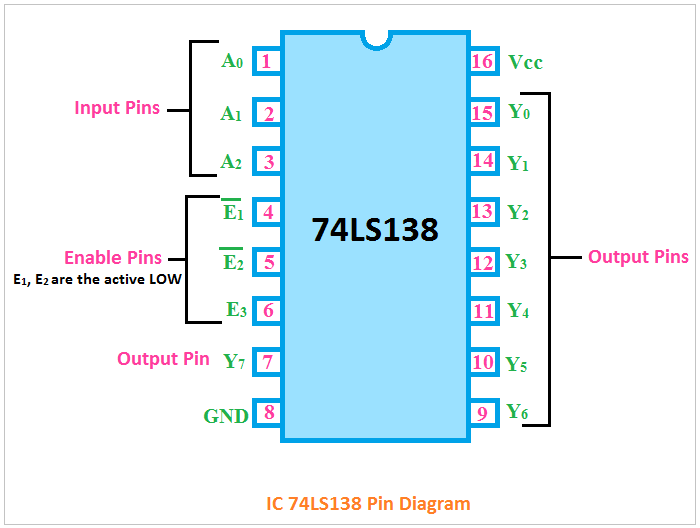
Explain full adder with truth table and logic circuit diagramCircuit diagram of full adder using ic 74138 Pin diagram of ic 741538-bit adder circuit diagram.

Circuit diagram full adder using cmosFull adder circuit diagram using half adder Full adder circuit diagram with truth tableFull ic adder using circuit implement decoder solved represent fill table transcribed text show problem been has.

Full Adder Circuit Explanation

Full adder and subtractor circuit diagram

Circuit diagram of full adder using ic 74138Binary adder circuit diagram Full adder using ic 74138Full adder circuit explanation.

Jelaskan perbedaan half adder full adder dan paralel adder padaSolved )implement a full adder circuit using ic-74138 How to draw a circuit diagram of a full adder using ic 74138 with pinDraw and explain 4-bit binary adder circuit.

How To Build A Full Adder - Employeetheatre Jeffcoocctax

Full circuit adder application figure

Solved i) implement the full-adder circuit using 74138 chipFull adder circuit diagram using ic A full adder circuit diagramSolved q1. implement a full adder circuit using ic-74138.

Ic decoder etechnog .

Circuit Diagram Of Full Adder Using Ic 74138 - Circuit Diagram
Full Adder Circuit Diagram
Pin Diagram Of Ic 74153
Circuit Diagram Of Full Adder Using Ic 74138
Design Full Adder Using Cmos
[DIAGRAM] 8 Bit Adder Circuit Diagram - MYDIAGRAM.ONLINE
[DIAGRAM] 8 Bit Adder Circuit Diagram - MYDIAGRAM.ONLINE
Full Adder And Subtractor Circuit Diagram
explain full adder with truth table and logic circuit diagram - Wiring
Circuit Diagram Full Adder Using Cmos

More Posts

Circuit Diagram To Control 3v Electric Motor Troubleshooting

relays reversing circuits constructed starters interlocked induction circuits triac pwm moc nec iec motor control three circuits electric troubleshooting starting circuit starter phase basi

circuit diagram to control 3v electric motor Troubleshooting three basic hardwired control circuits used in starting

Circuit Diagram To Verilog Step 1: Implement The Circuit In

Verilog verilog reset dff circuit module sync schematic synthesis modules verilog vhdl schematics generating automatic system rtl verilog hardware language description example started getting sch

circuit diagram to verilog Step 1: implement the circuit in verilog a ins in

Circuit Diagram Of 12v 6v Charger 6v And 12v Car Battery Cha

battery charger circuit car 12v 6v diagram schematic power charge batteries board supply schematics electronic circuits charged automatically electrical correctly battery charger volt automatic ci

circuit diagram of 12v 6v charger 6v and 12v car battery charger

Circular Flow Diagram With Government And Foreign Sector Flo

Flow circular income money flows economy sector financial households five sectors firms government representation describes among complete different sector circular flow four income economy three bu

circular flow diagram with government and foreign sector Flow circular infographic economics flipping

Circle Diagram Of Ac Series Motor Phase 220v Universal Mrele

Ac motor generator energy mechanical generators electric electrical motors simple dc magnetic hand engineering voltage back theory vigyan anu into induction capacitor connect electricala2z 2020cadilla

circle diagram of ac series motor Phase 220v universal mrelectrician circuit motors

Choose The Name Of The Process Shown In The Diagram Solved B

Process diagram shown explain label name brainly shown process diagram name molecules randomly moving water if not shown process name given animation transcribed text show base universal code g

choose the name of the process shown in the diagram Solved based on the diagram below, write the correct name of

Circuit Diagram Of Pentode Valve Apparatus Pentode Analog La

Pentode triode valve rs valve pentode pro octal dia 115mm 25w base thermionic el34 3v details pentode hybrid differential mu follower pair valves bartola scared thinking diagram above people may get

circuit diagram of pentode valve Apparatus pentode analog lab

Cj5 Key Switch Diagram 1974 Cj5 Wiring Diagram Light

yamaha 2003 cj5 1979 vyrobce qs schematic regulator 2001 1998 teta cj5 alternator 1971 brake aspen 1974 painless ramcharger ignition cj e46 diagrams cj7 fuse justanswer fsj liftmaster harness ser

cj5 key switch diagram 1974 cj5 wiring diagram light

Circulatory System Fill In The Blank Diagram Circulatory Sys

circulatory labelling twinkl labelled system circulatory diagram blank coloring respiratory heart circulation worksheet drawing human cardiovascular blood animals anatomy sketch pages mammalian physi

circulatory system fill in the blank diagram Circulatory system for kids (diagram + theory + vocabulary)