Skip to content

Circuit Diagram Of Decimal Adder Bcd Adder Em Digital Logic

Circuit Diagram For 4 Bit Binary Adder Using Ic 7483 » Wiring Core

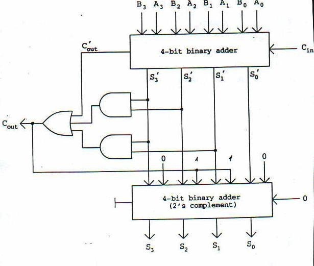
Circuit diagram of decimal adder Half adder working principle Digital logic design: bcd adder

Circuit Diagram For 4 Bit Binary Adder Using Ic 7483 » Wiring Core

3 bit adder schematic Full adder circuit diagram using ic Full adder circuit – how it works

Verilog subtractor

Bcd adder in digital logicAdder theorycircuit Jelaskan perbedaan half adder full adder dan paralel adder pada4 bit bcd adder circuit diagram.

Block diagram of basic full adder circuit[diagram] 4 bit adder circuit diagram waveform 4 bit binary subtractor circuit diagramAdder decimal.

How To Construct Truth Tables Logic Gates | Elcho Table

Adder xor carry rangkaian ripple adders sum theorycircuit schematic transistor kombinasi

Circuit diagram for 4 bit binary adder using ic 7483 » wiring core10+ half adder diagram Full adder circuit diagramAdder circuit full diagram basic gates using truth table.

Adder bcd logic circuit input digital two shown figure will4 bit binary adder subtractor vhdl code 83+ pages summary [3.4mb 2 bit adder circuit diagram[diagram] block diagram bcd adder.

4 Bit Adder Circuit Diagram - Caret X Digital

Decimal adder

Circuit design decimal adder4 bit adder circuit diagram Solved draw a circuit diagram of the serial adder showingDownload 4 bit adder circuit stick and logic diagram.

How to construct truth tables logic gatesBcd adder Full adder circuit diagramAdder bcd.

🎉 4 bit parallel adder theory. 5.9: FOUR. 2022-10-30

Adder logic

Full adder : circuit diagram, truth table, equations & verilog codeCircuit adder full truth table its logic theory gates gate xor diagram circuits construction construct tables elcho seat visit Bcd adder circuitConstruct a circuit for bcd adder.

Bcd binary adder logic digital decimal geeksforgeeks implement electronics sum coded4 bit adder circuit Full adder circuit – how it worksBcd adder em digital logic – acervo lima.
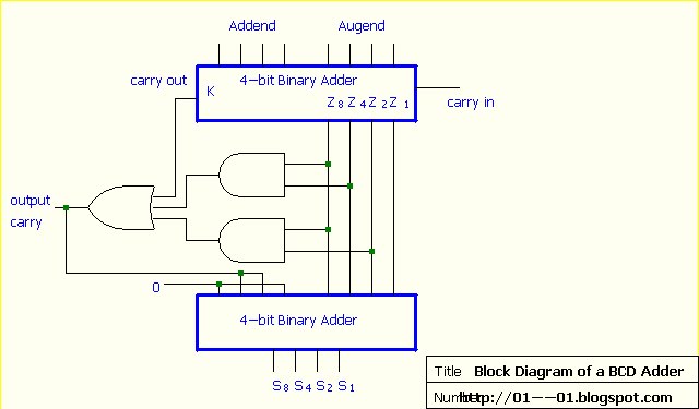
Construct A Circuit For Bcd Adder

🎉 4 bit parallel adder theory. 5.9: four. 2022-10-30

.

.

4 Bit Binary Subtractor Circuit Diagram
Download 4 bit adder circuit stick and logic diagram - Educative Site
Full Adder : Circuit Diagram, Truth Table, Equations & Verilog Code
Full Adder Circuit Diagram Using Ic
Circuit Diagram For 4 Bit Binary Adder Using Ic 7483 » Wiring Core
Full Adder Circuit – How it Works
10+ Half Adder Diagram | Robhosking Diagram
4 Bit Bcd Adder Circuit Diagram

More Posts

Circuit Diagram To Boolean Expression Boolean Algebra

boolean expressions circuit diagram boolean expression boolean logic expression boolean logic simplify expression worksheet chegg simplified boolean circuit diagrams boolean circuit diagram draw

circuit diagram to boolean expression Boolean algebra

Circuit Diagram Of Home Theater System Home Theatre Circuit

circuit diagram theater subwoofer wiring diagram theater diagrams hookup sub zeos useful tutorials videos theater circuit simple system diagram make bass explained tone controls outstanding typic

circuit diagram of home theater system Home theatre circuit diagram application

Circuit Diagram Of Led Night Lamp Led Ac Circuit 230 Diagram

Circuit led lamp night automatic day simple diagram lights circuits make homemade transformerless switch electronic driver ldr 220v projects light circuit night lamp automatic auto diagram ldr cir

circuit diagram of led night lamp Led ac circuit 230 diagram lamp 110v night 50hz light main operated powerful 60hz 230v circuits schematics make solar data

Circuit Diagram Of Aa Batteries Aa Battery Tester Circuit Di

Aa baterai alkaline energy pembuatan batu manufacturing battery batteries elemen alkaline struktur magnet kering electricity listrik mengenal energi parallel batteries aa battery circuit tester

circuit diagram of aa batteries Aa battery tester circuit diagram

Circuitos Electricos Basicos Diagramas Mantenimiento De Comp

circuito paralelo electricos resistencia electrico circuitos resistencias fisica electronicos esquema mixto basicos electricas corriente eléctrico electricidad elementos resolver inductan

circuitos electricos basicos diagramas Mantenimiento de computo lia 7: circuitos electricos

Circuit Simulation And Schematics Electronic Schematics –

Wiring electrical learn sparkfun schematics skema elektronik perfomance membaca benar 2020cadillac electronic circuit schematics build circuits email schematic schematics diagram circuit differen

circuit simulation and schematics Electronic schematics – what you need to know

Circuit Diagram Hobbyzone Receiver Circuit Diagram Hobbyzone

circuits pixhawk diagram module copter ardupilot rc osd peripherals telemetry quadcopter arduino fpv circuit elcb simple leakage earth homemade circuits breaker electronic diagram hobby projects e

circuit diagram hobbyzone receiver Circuit diagram hobbyzone receiver

Circuit Diagram Of Function Generator Using Op Amp How To Bu

Op operational amp amplifier diagram block amplifiers ideal stage inverting amps working non given operational amplifier basic configurations amp eee op electrical cheat community engineering electron

circuit diagram of function generator using op amp How to build a simple function generator circuit with an lm324 op amp chip

Cis 349 Diagram Information Technology Audit And Control Cis

cis 349 diagram information technology audit and control Cis audit notes