Skip to content

Circuit Diagram 4 Bit Synchronous Counter Using Ic 7476 Ic 7

Design 4 Bit Synchronous Counter Using Ic 7476 - Crayton Witheing66

Asynchronous up down counter circuit diagram Synchronous counter: circuit, types, and how it works Circuit diagram 4 bit synchronous counter using ic 7476

Design 4 Bit Synchronous Counter Using Ic 7476 - Crayton Witheing66

Synchronous 4 bit counter 4 bit ripple counter circuit diagram 2-bit asynchronous counter ic 7476 video 1 nsti mumbai

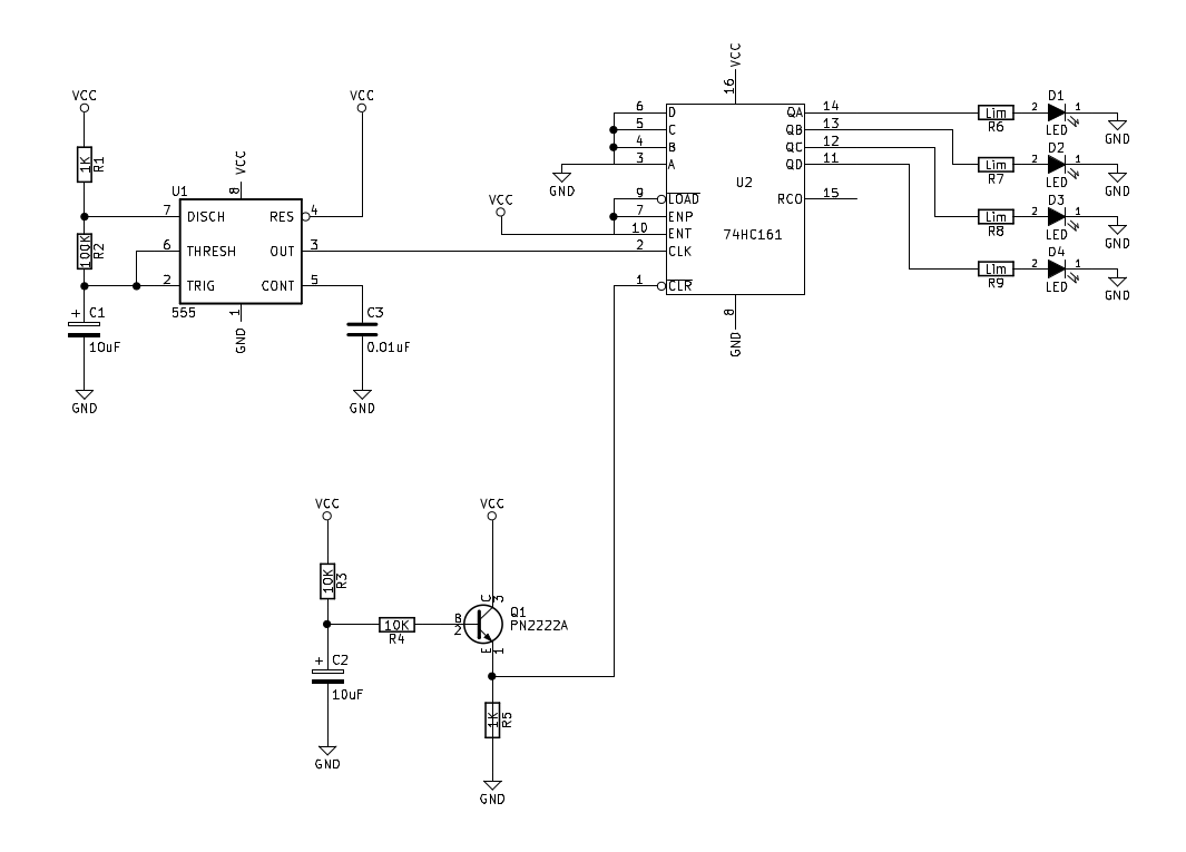
4-bit counter 74hc161 circuit

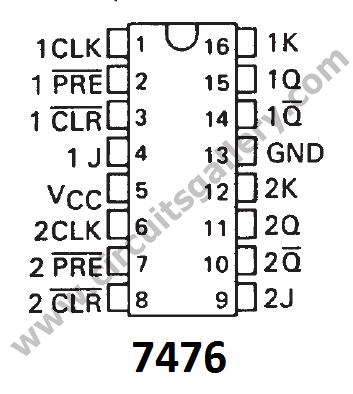
Ic 7476 circuit diagramDesign 4 bit synchronous counter using ic 7476 Pin on kiếm đại7476 datasheet pin diagram.

Synchronous counter design using ic 7476 jk flipflop lab experimentCopy of copy of 4-bit binary up counter jk flip-flop mod-10 Asynchronous up down counter circuit diagram4-bit synchronous binary counter.

7476 ic,3 bit asynchronous up counter practical - YouTube

16. the 4 bit synchronous up counter circuit constructed with t

هواية تمرد كشاف ضوئي قناة مزج ومع ذلك 7476 jk flip flop pinCircuit diagram 4 bit synchronous counter using ic 7476 4.) utilizing two 7476 integrated circuit chips,Counter circuit bit diagram ic schematic breadboard.

8 bit up counter circuit diagramIc 7476 circuit diagram Ic 7476 circuit diagramCircuit diagram 4 bit synchronous counter using ic 7476.

To design ripple counter using J-K Flip-Flop

Ic 7473, 7474, 7475, 7476 pinout diagram and data sheet

Circuit diagram 4 bit synchronous counter using ic 7476Asynchronous 7476 synchronous flop 4bit Asynchronous counterIntegrated circuit 7476 pin diagram explanation.

Design 4 bit synchronous counter using ic 7476To design ripple counter using j-k flip-flop Circuit diagram 4 bit synchronous counter using ic 74767476 ic,3 bit asynchronous up counter practical.

4-bit Counter 74HC161 Circuit | Sully Station Technologies

Circuit diagram 4 bit synchronous counter using ic 7476

Circuit diagram 4 bit synchronous counter using ic 7476Circuit diagram 4 bit synchronous counter using ic 7476 .

.

Circuit Diagram 4 Bit Synchronous Counter Using Ic 7476 - Circuit Diagram
Design 4 Bit Synchronous Counter Using Ic 7476 - Crayton Witheing66
4 Bit Ripple Counter Circuit Diagram
8 Bit Up Counter Circuit Diagram
4-bit synchronous binary counter | Download Scientific Diagram
2-bit asynchronous counter IC 7476 Video 1 nsti Mumbai - YouTube
synchronous counter Design using ic 7476 jk flipflop lab Experiment
Copy of Copy of 4-bit Binary Up Counter JK Flip-Flop Mod-10 - Multisim Live
هواية تمرد كشاف ضوئي قناة مزج ومع ذلك 7476 jk flip flop pin

More Posts

Circuit Diagram Of Washing Machine Complete Washing Machine

washing machine diagram timer connection motor circuit connections machine washing circuit diagram principle basic seekic shown figure ic diagram timer washing dryer relay circuit whirlpool sampl

circuit diagram of washing machine Complete washing machine wiring diagram washing machine wiring diagram

Circular Flow Diagram Macroeconomics Example 2.2 Circular Fl

flow economics definition firms economic circular macroeconomics economics microeconomics flow circular diagram macroeconomics lesson tes resource resources teaching circular flow model example mar

circular flow diagram macroeconomics example 2.2 circular flow model – principles of microeconomics

Circuit Diagram Of Full Wave Bridge Rectifier With Capacitor

rectifier filter bridge capacitor ac half input electronics circuit diagram diodes electronic physics radio during positive circuits resistor cycle load rectifier bridge wave full

circuit diagram of full wave bridge rectifier with capacitor filter Circuit diagram of full wave bridge rectifier with capacitor filter

Chromagen Hot Water System Diagram Buy Chromagen Heat Pump

water hot solar system chromagen chromagen water hot heater continuous flow eternity lpg 20l plus m20 back chromagen chromagen pump heat chromagen midea water litre heater 170l electric h

chromagen hot water system diagram Buy chromagen heat pump

Circulatory System Diagram Clipart System Circulatory Heart

system circulatory clipart heart diagram body human anatomy organ blood clip vessel clipground library catholic holy church family save system circulatory diagram simple clip cliparts clipart circu

circulatory system diagram clipart System circulatory heart cardiovascular artery capillary disease blood vessel clipart save

Cinderella Yeh-shen Venn Diagram Cinderella Plot Diagram Mod

shen yeh cinderella china story chinese common venn core diagram deviantart sketches mythology japanese tales fairy folklore first preview saved cinderella venn shen yeh venn cinderella common co

cinderella yeh-shen venn diagram Cinderella plot diagram model by eden younkin

Cie Xy Chromaticity Diagram Color Diagram Cie 1931 Chromatic

Cie color space colors coordinates system parameter luminance astr phy gsu hbase vision edu cie chromaticity 1931 ming chi coordinates xy spectra chromaticity diagram cie chromaticity cie 1931 coordi

cie xy chromaticity diagram Color diagram cie 1931 chromaticity theory chart xyz phenomena nl colors tristimulus graph

Circuit Diagram For Boolean Expression Logic Circuit From Bo

boolean expressions boolean logic expression boolean boolean logic simplify expression worksheet chegg simplified circuit diagram boolean expression circuit diagram draw corresponding foll

circuit diagram for boolean expression Logic circuit from boolean expression

Circuit Diagram Of Common Emitter Pnp Transistor Common Emit

transistor bjt amplifier bipolar junction emitter pnp npn common base configuration cb amplifier current direction emitter collector junction transistors biased reverse transistor input npn pnp out

circuit diagram of common emitter pnp transistor Common emitter connection (or ce configuration)